


Fiber Patch Cable Quality
To provide customers with high-quality fiber patch cables, manufacturers carry out a series of tests during the designing and manufacturing process. These optical fiber tests are critical for nearly every type of fiber network. It is necessary for not only vendors but also end users to learn what these tests are to know fiber patch cable quality and then decide the feasibility in your application. This post is going to introduce the three tests: 3D metrology, insertion loss (IL) test & return loss (RL) test, and endface clarify, which provide end users with confidence that the patch cables are high-quality and address their importance to fiber patch cables.
1. 3D Metrology Test: Guarantee of High-Quality Connector Endface
3D metrology test, or three-dimensional surface measurement, is a key test for controlling the performance of fiber optic connectors. In the production and functioning of fiber optic cable components, 3D interferometer, as the instrument to perform optical interferometry, plays an important role to enable vendors to inspect the fiber endface and control strictly the endface dimension. The three main properties measured are the radius of curvature, apex offset, and fiber height.
Radius of Curvature
As you can see in the image below, radius of curvature is the roundness of the ferrule’s endface. The radius of curvature of high-quality fiber patch cable connector endface should be controlled in a certain range. Too tight of a radius will put too much compression on the glass and too loose will put too much on the surrounding ferrule with not enough glass compression. Too much or too little radius can cause light scatter or inadequate physical contact for optimal signal transfer. Only a proper radius will allow for right compression and maximum performance.
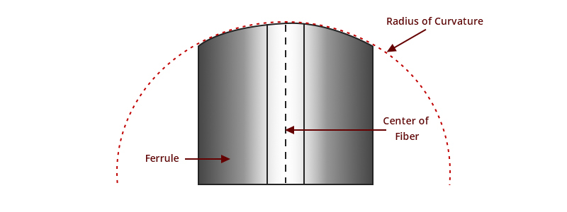
Apex Offset
Apex offset refers to the linear distance between the highest point of polished ferrule endface and the center of fiber. It is a key term to amplify during polishing process. Incorrect polishing can be the reason for apex offset.
In theory, mated connectors with centered apex offsets should have perfect core-to-core connection, without any air gap. If there is a large apex offset, an air gap can be created, resulting in high IL and RL. Optical connectors with PC or UPC ferrules should set the apex offset at 0 degrees vertical angle during polishing. When ferrule is perfectly perpendicular to the polishing surface, the apex will be the exact center of fiber. APC ferrule is another case. The ferrule should be at an angle of 8 degrees to the fiber, instead of perfectly vertical.
Fiber Height
Fiber height is the height that a fiber core extends from the ferrule surface. The fiber height should be not too high or too low. If too high, the fiber may bear the risk of being damaged when mated; if too low, gap will occur between the mated connector, resulting in increased insertion loss. Especially for those transmissions with stringent insertion loss requirements, gaps are certainly something you should avoid.
Standard 3D interferometer values are different in fiber modes and polish styles, thus the specific products should meet or exceed relevant industry-accepted endface geometry standards. The following chart is the endface geometry requirements of MTP single mode trunk cable connector based on IEC/PAS 61755-3-31 and IEC/PAS 61755-3-32.
2. IL & RL Test: Critical Measurement for Optical Deployment
IL, or insertion loss, is the loss of signal power resulting from inserting a device in a transmission line or optical fiber. RL, or return loss, refers to the loss of signal power reflected to the light source. In Reference to Insertion Loss and Return Loss for Fiber Connectors, IL and RL definition, the causes and tips for optimizing the values of the insertion/return losses are introduced.
No matter for the manufacturing process or installation, IL & RL test matters a lot. For optical cable vendors, the insertion loss and return loss tested should be conformed to a series of corresponding standards. For example, TIA standards specify a maximum fiber connector insertion loss of 0.75dB, which is considered as the worst-case situation. For most fiber connectors in the market, they have a range of 0.3dB to 0.5dB for standard loss and 0.15dB to 0.2dB for low loss. Manufacturers use IL & RL tester/meter to check if the values are within the normal limits so that the end-users could receive qualified products.
For end-users, apart from taking the IL & RL value written in the product specification lists for reference to design the optical link and choose other devices and assemblies based on the reference value, it is also possible to test by yourself if testing tools are available. It helps installers troubleshoot and identify faulty system components. OTDR, OFDR are frequently used techniques used for measuring return loss.
3. Endface Clarity: Necessary Inspection to Ensure Endface Cleanliness
We have talked about fiber cleaning a lot of times, to be more specific, cleaning the connector endface. Endface clarity is an essential procedure in optical fiber maintaining no matter 40 years ago or today. Manufacturers do endface inspection to confirm if there are contaminants, scratch or crack over the connector endface. Almost every fiber optic engineer has fiber optic cleaning testers/tools such as pen cleaner or cassette cleaner, which frequently appear while installing cables.
Why is it important to do endface clarity? The cleanliness and smoothness of the fiber optic connector endface is one of the basic and important procedures for maintaining high quality fiber optic connections. It is different from any other kind of cleaning due to the deformation of connector endface and the particle contaminants reside on it. Even microscopic dust can increase return loss and even cause potentially permanent damage to the connectors. Moreover, the dust between two endfaces can scratch the surfaces, causing an air gap or misalignment between fiber cores, which degrades the optical signal. Since these contaminants are so tiny to see without a microscope, if you mate a dirty plug, the other plug can also get contaminated. Therefore, even though vendors have done endface clarity during fiber optic connector testing, every time before connectors are mated or after they are un-mating, you should be diligent in inspecting endfaces and cleaning them.
Conclusion
In summary, the fiber optics industry tries to improve the fiber connector’s quality by exploring the key parameters that need to be measured. Also, industry associations and committees do several surveys to define the manufacturing criteria for fiber quality assurance. If the fiber patch cables have gone through three abovementioned tests and the test results meet the standards, they will be competent to contribute to the high-quality optical transmission. For end-users, it is required to check whether vendors have carried out these tests and affirm the test parameters with the test reports provided by manufacturer.
source: community.fs
Related products...
fiber-optic-cable
fiber-optic-cable
12-core OBUC (2×6), single-mode NZDSF, PBN brand dry fiber optic cable
fiber-optic-cable
[ratings]