


Duct Installation of Fiber Optic Cable
Fiber optic cable is usually (but not always) installed in an innerduct that provides mechanical protection for the fiber optic cable. Generally, the duct is available in plastic, concrete, steel, iron and so on. As fiber optic cable is sensitive to excessive pulling, bending and crush forces, much care shall be taken to avoid cable damage during its duct installation. Methods of duct installation, installation preparation and procedures would be covered in this article.
Installation Methods of Fiber Optic Cable into Duct
Generally, there are two approaches for optical cable installation into a duct, pulling method and air blowing method.
Pulling Method
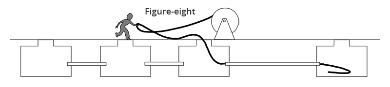
“Pulling Method” refers to cable installation into a pre-installed underground ducts by manual pulling or by puller machine. In this method, cable is pulled through duct with the help of pre-installed rope inside the duct. This pulling method is generally preferred in access networks where underground ducts are not continuous for more than 200 to 300 meters. Under this condition, the fiber cable needs to be stored in coil form at each manhole/handhole available at every 200 to 300 meters. Hence, fiber optic cable installation into a duct using a pulling method is suitable to apply within short distances.
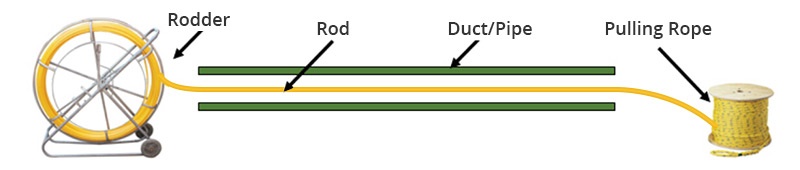
Limitations: Optical fiber cables must be handled in compliance with their stated design ratings. Handling crews must be familiar with the cable’s design ratings and the critical events during installation where design limits may be approached.
Air Blowing Method
Cable installation by using high speed air flow combined with additional mechanical pushing force is called as “air blowing”. Air blowing method includes high air speed blowing and push/pull (piston) blowing. The basic principle is injecting the compressed air into the duct and then they flow at high speed through the duct and along the cable. Standard optical fiber cables (like uni-tube, multi-tube, unarmored & armored), microduct cables, and micro-ducts can be installed by using this method. This method is applicable to continuous lengths of more than 1000 meters.
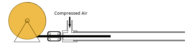
Limitations: Special air blowing equipment are required for air blowing method. Air blowing of fiber cable into duct systems requires continuous run of inner-duct and pressure testing for integrity. Quality of inner-duct joints is critical to the success of air blowing techniques.
Pulling Method VS Air Blowing Method: How to Choose?
Site conditions, availability of machinery and resources are crucial factors for choosing cable installation method. The differences between pulling method and air blowing method for optical fiber cable installation are shown in the table below.
As a rule of thumb, air blowing method for fiber optic cable installation is more favored than pulling method due to improved installation efficiency, particularly in longer ducts with multiple bends and undulations and savings in manpower and installation time.
Preparations for Duct Installation Using an Air Blowing Method
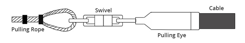
General precautions should always be applied when handing optical cable, such as not exceed the cable’s stated maximum pulling tension and stated bending radius, as well as not exceed the cable’s maximum crush load, and etc. In addition, other general safety precautions should be paid much attention as well. Before installation begins, construction planning also should be initialed. Last but not least, necessary equipment and materials are required for every installation, including inner-duct, cable pulling lubricants, a pulling eye or grip, a swivel, the cable blower equipment, and etc. For detailed information about preparation for duct installation, you should read installation manual carefully.
Duct Installation Procedure by Using Air Blowing Method
Step 5 to Step 11 are about setting up inner-duct and cable blower unit(s). Please refer to detailed equipment procedures on manual.
Conclusion
Fiber optic cable installation into the duct provides both extra protection for optical fiber cable and an opportunity for future cable expansion. Optical fiber cable installation into the duct has widely been applied for telecommunication application so far.
Source: community.fs
Related products...
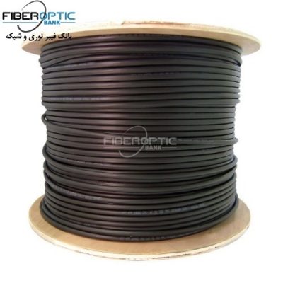
fiber-optic-cable
fiber-optic-cable
OFO fiber optic cable 24 core (2*12) , singlemode ADSS-SPAN80
fiber-optic-cable
[ratings]