


Test Fiber Optic Cables
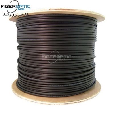
A fiber optic cable refers to any cord that uses light to carry signals from one source to another. They are faster than traditional wires and are commonly used to hook up high-speed internet servers, complete important mechanical tasks, and operate surgical instruments. While there are many different fiber optic cable tests, the most common version is an insertion loss test, also known as an attenuation, jumper, or connectivity test. This test requires a special testing kit and protective eyewear, but it will help you diagnose problems with the cable’s connectivity, power, and reliability.
Setting Up the Test
Perform an insertion loss test to assess the power and connection. Insertion loss refers to the amount of power and information that is lost as light travels from one end of a cable to another. An insertion loss test helps you identify whether the computer, network, or power source is the root of your connectivity problem. It also assesses how well a cable can handle a signal, if any information is lost as it travels through the cable, and whether your cable is operating efficiently and safely or not.
- An insertion loss test is also known as an attenuation or jumper test.
- You cannot perform an insertion loss test on more than 1 cable at a time.
Purchase an insertion loss testing set with an optical source and meter. To perform an insertion loss test, buy a testing kit from a fiber optic or IT company. This kit includes an optical source, which fires a signal into the cable, and an optical meter, which reads the signal at the other end. The difference between the power output of the source and the reading on the meter will tell you how much information you’re losing in the cable.
- The optical source is also known as a light source or power source.
- An insertion lost testing kit costs $500-3000, depending on how much functionality you want in your testing kit.
- Test kits typically come with 2 jumper cables, which you need to complete the test. If they don’t, purchase 2 fiber optic jumper cables separately.
- You also need 2 fiber optic patch panels. A patch panel is basically an array of different ports for patching 2 cables together without splicing them (like a breadboard). A single patch panel costs $10-250, depending on how many ports you need. For an insertion loss test, you only need 2 ports on each panel.
Change the wavelength settings on both meters to the same number. Turn your optical source and meter on and let them warm up for 5 minutes. Then, change the “wavelength” setting on both meters so that they match. The specific wavelength you use depends upon the type of cable that you have, so consult the manufacturer or ask the network administrator to determine what type of cable you’re testing.
- For a plastic fiber optic cable, use 650-850 nm. For a multimode index cable (that isn’t yellow and has 2 ports at each end), use 850-1300 nm. Set your meters to 1310-1625 nm for single-mode fiber cables (which have 2 ports on each end and is almost always yellow).
- Every testing kit has different menu controls and buttons. Some machines use dials, while others use digital screens to change wavelength settings and send test signals. Consult your testing kit’s instruction manual to determine how your specific testing kit functions.
- For fiber optic cables, the wavelength is always measured in nanometers (nm).
Performing the Test
Test each jumper cable by running a test signal through your cables. Connect your first jumper to the port on the top of the optical source. Plug the other end of the same cable into your optical meter. Then, press the “test” or “signal” button to send a signal from the source to the meter. Check the reading on the meter screen and source screen to see if the numbers match. This reading will be in dBm (decibel milliwatt) and/or dB (decibel). If the numbers don’t match, replace the jumper cable with a new one. Perform this test on your other jumper cables.
- Clean the terminal on each end of the cable with a fiber optic cleaning solution if you don’t see the right power input on the screen.
- Most testing kits will display both dBm and dB. The dB reading refers to the optical loss—the amount of information lost. The dBm measurement refers to the power of the overall signal (the amount of energy received).
- If the numbers on the screen are measured in OL or Ω, you have the meters set to test continuity, not insertion loss. Consult your manual if you can’t figure out how to change the test setting.
Connect the jumper cables to ports on the patch panel. Remove the cable you were testing and connect your first jumper to the optical source. Plug the other end into any port on the first patch panel. Take your second cable and plug it into the optical meter. Plug the other end of that cable into any port on the second patch panel.
- Some kits have dedicated cables for each meter. On other kits, the cables are interchangeable. Check each cable by inspecting the ports and covers to see if they’re stamped with the words “power” or “transmitter.” These cables must be connected to the power source. The other cable may say “receiver” or “meter.”
Run the cable you’re testing to the patch ports with the jumper cables. Take the cable that you’re testing and plug either end into the port on the opposite side of the jumper that is connected to the optical source. Take the other of the cable that you’re testing and plug it in to the port on the opposite side of the meter’s cable.
- You may need to slide an adaptor on to the terminals of the test cable to connect it to the patch panel, depending on what type of fiber optic cable you’re testing.
- If you’re testing a cable with 2 ports on each end, only one of them must connect to the port with the jumper cable on the opposite side. Plug the second port into an empty slot next to the connected terminal.
Send a power signal from your optical source to the meter. Check your connections to ensure that your cables are all connected through the patching ports. Then, press the “test” or “signal” button to perform your insertion loss test. The numbers on the meter should pop up after 1-2 seconds. If they don’t, there’s probably a problem with your patch panels and you should use a different set. Once you get a dB and dBm reading, your test is complete.
- Don’t worry if the numbers bounce up and down for a few seconds. This is simply the meter interpreting the results from the test.
Read the dB results to assess the accuracy of the cable’s connection. What your results mean depends entirely on the cable and its function. Generally speaking, a dB loss between 0.3 and 10 dB is acceptable. The higher the dB reading is on your screen, the more information you’re losing. That means that a cable with a dB of 10 is losing more information than a cable with a dB of 8.
- You’re never going to add light from one end to the other, so this number can never be positive. On some testing kits, they put a negative sign (-) next to the number to indicate that you’re losing light/information, but some kits don’t bother since it can never be positive.
- A perfect reading is nearly impossible. You usually lose a little power and information through the terminal ports. The length of the cable can also cause some information to be lost.
Assess the cable’s dBm to determine how strong the cable is. In terms of the cable’s power, a dBm between 0 and -15 is generally okay, but the power level is heavily dependent on what the cable is for. Power loss is a much bigger issue if the cable is hooked up to a surgical instrument, but it’s not a big deal if you’re simply connecting a modem to a router. This number can be negative or positive, so pay attention to the symbol at the front of the number
- This number can be positive since anything over 1 milliwatt is considered a positive charge. The cable isn’t technically adding power.
- If the readings are in an acceptable range and you’re still experiencing problems with the cable, the issues are likely not the cable itself.
Source: wikihow
Related products...
fiber-optic-cable
fiber-optic-cable
SGGC fiber optic cable 24 core (6*1 NZ+3*6 SM) , singlemode ADSS-SPAN110
fiber-optic-cable
[ratings]