


Twisted-Pair Cable Connectors
Currently, twisted pair copper cabling (particularly the UTP cabling) is the most ubiquitous for LAN and telephone installations. For twisted pair connection, you may need a crimping tool to push the metal contacts inside the cable connector onto the individual conductors in the cable. This tutorial tells you how to install twisted pair cable connectors step by step.
Twisted-Pair Cable Connectors
There are mainly two types of cable connectors used for twisted pair connection in voice and data communication installation.
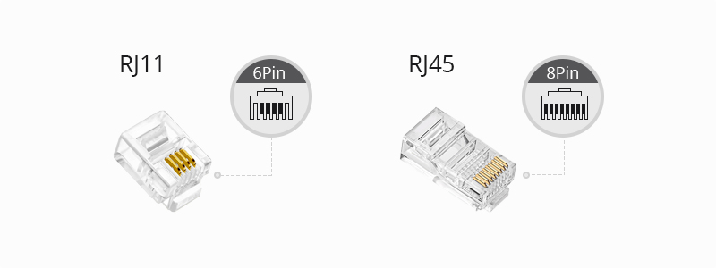
RJ11 Connectors
RJ11 connectors typically have only 6 positions and 4 or 2 contacts. They are not internationally standardized, but used to be a very popular choice for both commercial and residential telephone applications due to their simplicity and small forms.
RJ45 Connectors
RJ45 connectors normally have 8 positions and 8 contacts. Therefore, RJ45 connectors are larger than RJ11 connectors in forms. An RJ45 connector is usually used for data transmission in scenarios such as monitoring projects and general cabling in the equipment room. It is an indispensable supporting role in Ethernet and is generally used at both ends of a network cable to connect various network devices, such as computers, routers, switches, etc.
Notice: Due to the different structure of RJ45 and RJ11 connectors, the wiring sequence standard and applications are also different. It is not recommended to use RJ11 plugs for RJ45 jacks as it may cause damages on the devices.
Types of Twisted Pair Cables
There are two types of twisted pair cables according to the RJ connectors.
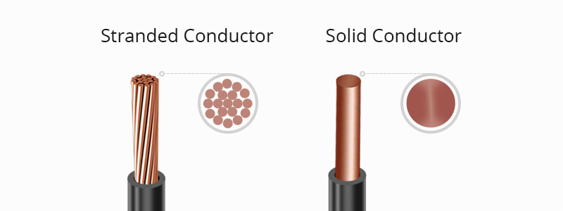
Stranded-Conductor Twisted Pair Cable
Stranded-conductor twisted-pair cable is made up of many tiny hairlike strands of copper twisted together into a larger conductor. These conductors have more surface area to make contact with but are more difficult to crimp because they change shape easily. Because of their difficulty to connect, they are usually used as patch cables.
Solid-Conductor Twisted Pair Cable
Most UTP cable installed in the walls and ceilings between patch panels and wall plates is solid-conductor cable. Although they are not normally used as patch cables, solid-conductor cables are the easiest to connect, so many people make their own patch cords out of solid conductors.
Tools for Installation of Twisted Pair Cable Connectors
There are mainly three tools which are needed in the coming installation.
Fiber Cable Stripper
The first tool is a cable-jacket stripper. It will only cut through the outer jacket of the cable, not through the conductors inside. Many different kinds of cable strippers exist, but the most common are the small, plastic ones that easily fit into a shirt pocket. They are cheap to produce and purchase.
Cable Connector Crimper
You will also need a crimping tool. A cable crimper is used to finish the connection between network cables and connectors. But there are specific types of crimpers used for specific cables. Some crimpers can finish both RJ45 and RJ11 connectors. So, make sure you choose the right crimping tool.
Network Cable Tester
The last tool you are going to use is a cable tester. This device tests for a continuous signal from the source connector to the destination and also tests the quality of that connection.
Tips: Normally, the above-mentioned tools come as a network installation tool kit to meet multiple needs. It may have everything you need to get started.

Installing Steps
Now we will go over the steps for installing the connectors. Pay particular attention to the order of these steps and be sure to follow them exactly. Equipment from some manufacturers may require you to perform warning slightly different steps. Check the manufacturer’s instructions before installing any connector.
Step 1
Measure the cable you want to put ends on and trim it to the proper length using the cable cutter.
Step 2
Use the cable stripper to strip about 1.5″ of the jacket from the end of the cable. Then, rotate the stripper around the cable twice. This will cut through the jacket.
Step 3
Remove the stripper from the cable and pull the trimmed jacket from the cable, exposing the inner conductors. If a jacket slitting cord (usually a white thread) is present, separate it from the conductors and trim it back to the edge of the jacket.
Step 4
Untwist all the inner conductor pairs and spread them apart so that you can see each individual conductor.
Step 5
Line up the individual condutors so that the color code matches the color-coding standard you are using.
Step 6
This step includes two points. First, trim the conductors so that the ends are even with each other, making sure that the jacket of the cable will be inside the connector. Second, the total length of exposed connectors after trimming should be no longer than 0.5″ to 0.625″.
Step 7
Insert the conductors in the connector, ensuring that all conductors line up porperly with the pins as they were in the previous step. If they don’t line up, pull them out and line up. Do this carefully, as it’s the last step before crimping on the connector.
Step 8
Carefully insert the connector and cable into the crimping tool, which has two dies that will press into the connector, and push the pins in the connector into the conductors inside the connector. Now the installation is done.
After the whole installation, you should check to ensure all conductors are making contact and that all pins have been crimped into their respective conductors. If the connector didn’t crimp properly, cut off the connector and redo it.
Source: community.fs
Related products...
fiber-optic-cable
AMP fiber optic cable 12 core (1*12), multimode OM1, Armored
fiber-optic-cable
[ratings]