


What Is Optical Fiber Dispersion?
Optical fiber dispersion describes the process of how an input signal broadens/spreads out as it propagates/travels down the fiber. Normally, dispersion in fiber optic cable includes modal dispersion, chromatic dispersion and polarization mode dispersion.
Modal Dispersion
Modal dispersion is a distortion mechanism occurring in multimode fibers and other waveguides, in which the signal is spread in time because of different propagation velocity for all modes. As we know, light rays entering the fiber at different angles of incidence will go through different paths/modes. Some of these light rays will travel straight through the center of the fiber (axial mode) while others will repeatedly bounce off the cladding/core boundary to zigzag their way along the waveguide, as illustrated below with a step-index multimode fiber. Whenever there is a bounce off, modal dispersion (or intermodal dispersion) happens. The longer the path is, the higher the model dispersion will be. For example, the high-order modes (light entering at sharp angles) have more model dispersion than low-order modes (light entering at smaller angles).
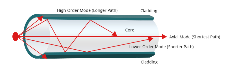
Multimode fiber can support up to 17 modes of light at a time, suffering much modal dispersion. Whereas, if the fiber is a single mode fiber, there will be no modal dispersion since there is only one mode and the light enters along the fiber axis (enters in axial mode) without bouncing off the cladding boundary.
However, things are different if one uses a graded-index multimode fiber. Although the light rays travel in different modes as well, the modal dispersion will be greatly decreased because of the various light propagation speeds. For more details, refer to Step-Index Multimode Fiber vs Graded-Index Multimode Fiber.
Chromatic Dispersion
Chromatic dispersion is a phenomenon of signal spreading over time resulting from the different speeds of light rays. The chromatic dispersion is the combination of the material and waveguide dispersion effects.
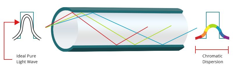
Material dispersion is caused by the wavelength dependence of the refractive index on the fiber core material. Waveguide dispersion occurs due to dependence of the mode propagation constant on the fiber parameters (core radius, and difference between refractive indexes in fiber core and fiber cladding) and signal wavelength. At some particular frequency, these two effects can cancel each other out giving a wavelength with approximately 0 chromatic dispersion.
What’s more, chromatic dispersion isn’t always a bad thing. Light travels at various speeds at different wavelengths or materials. These varying speeds cause pulses to either spread out or compress as they travel down the fiber, making it possible to customize the index of refraction profile to produce fibers for different applications. For example, the G.652 fibers are designed in this way.
Polarization Mode Dispersion
Polarization mode dispersion (PMD) represents the polarization dependence of the propagation characteristics of light waves in optical fibers. In optical fibers, there is usually some slight difference in the propagation characteristics of light waves with different polarization states. When the light is defined as an energy wave or energy region, it possesses 2 mutually perpendicular axes, namely the electromotive force and magnetomotive force. The moment the energy inside these two axes transfers at different speeds in a fiber, PMD occurs.
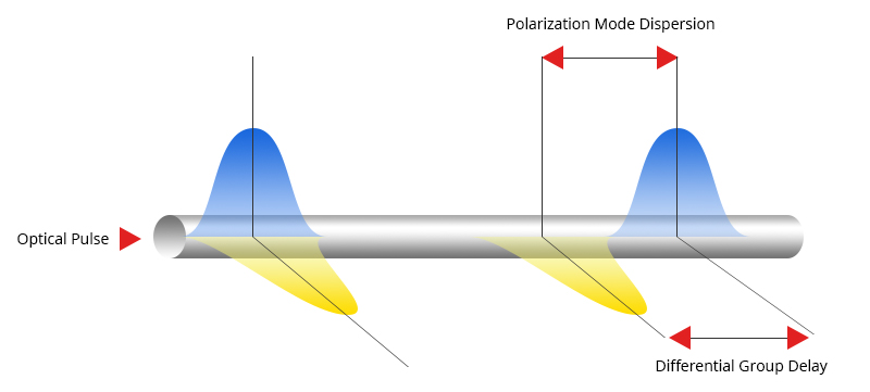
PMD has small effects for networks whose link speeds are lower than 2.5 Gbps even if the transmission distance is longer than 1000 km. However, as speeds increase, it becomes a more important parameter especially when the speeds are over 10 Gbps. In addition to the major inherent PMD caused by the glass manufacturing process, the PMD can be affected or caused by the fiber cabling, installation and the operating environment of the cable as well.
How to Make Fiber Dispersion Compensation?
Although optical fiber dispersion does not weaken the signal, it shortens the distance that signal travels inside optical fibers and blurs the signal. For example, a pulse of 1 nanosecond at the transmitter will be spread out to 10 nanoseconds at the receiver, resulting in signals not properly received and decoded. Therefore, it is important to reduce optical fiber dispersion or make dispersion compensation in long-haul transmission like DWDM systems. Here, we will introduce three compensation strategies or techniques to compensate for the fiber dispersion.
Dispersion Compensation With DCF
In DCF (Dispersion Compensating Fiber) technique, one can use a fiber having large negative dispersion alongside a typical fiber. The number of light distributed by a traditional fiber is reduced or maybe nullified by using a dispersion compensating fiber having a really giant value of dispersion of opposite sign as compared to that of normal fiber. There are primarily 3 schemes (fiber-pre, post or symmetrical) which will be used for dispersion compensation. And the dispersion compensating fibers are used extensively for upgrading the installed 1310nm optimized optical fiber links for operation at 1550nm.
Dispersion Compensation With FBG
Fiber Bragg Grating (FBG) is a reflective device composed of an optical fiber that contains a modulation of its core refractive index over a definite length. By applying FBGs, the dispersion effects can be dramatically decreased in long transmission systems like 100 km. The fiber grating reflects light-weight propagating through the fiber once its wavelength corresponds to the modulation regularity. Using FBGs for dispersion compensation may be a promising approach since FBGs are passive optical element fiber compatible, having low insertion losses and prices. The FBGs can not only be used as filters for dispersion compensation, but also be used as sensors, wavelength stabilizers for pump lasers, in narrow band WDM add drop filters.
Dispersion Compensation With EDC
Electronic Dispersion Compensation (EDC) is a method using electronic filtering (also known as equalization) to compensate for dispersion in an optical communications link. The filtering can be included in a communications channel to compensate for signal degradation caused by the medium. EDC is typically implemented with a transversal filter, the output of which is the weighted sum of a number of time-delayed inputs. EDC solution has the ability to automatically adjust the filter weights according to the characteristics of the received signal, which is known as adaptation. EDC can be used both in single mode fiber systems and multimode fiber systems. Furthermore, it can be combined with other functions on 10-Gbit/s receiver ICs. It can get significantly reduced transmitter cost for single mode fiber systems or increased transmission distance for multi-mode systems at a small receiver cost penalty.
Summary
Although optical fiber dispersion tends to temporally spread and distort signals in many ways, it is not always bad for the transmission of telecom signals in fiber optic links. Actually, it is better to have some amount of dispersion when using wavelength division multiplexing because it could mitigate nonlinear effects.
Source: community.fs
Related products...
fiber-optic-cable
fiber-optic-cable
fiber-optic-cable
[ratings]